
FREE Shipping & Return
Money Back Guarantee
24/7 Online Support
Related products
-

5V MINI USB HUMIDIFIER DIY KIT MIST MAKER AND DRIVER CIRCUIT BOARD
₨ 350 Add to cart -

50KG HALF-BRIDGE EXPERIMENTS BODY SCALE LOAD CELL SENSOR
₨ 150 Add to cart -
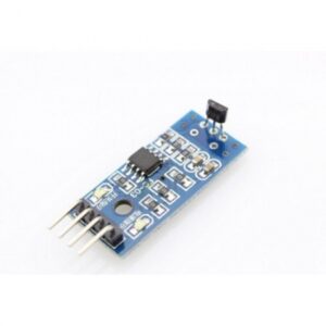
3144 HALL SENSOR MODULE MOTOR WITH LM393 SPEED SENSOR MODULE
₨ 120 Add to cart -
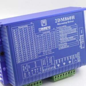
2DM860H DIGITAL MICROSTEP DRIVER STEPPER MOTOR CONTROLLER 32BIT DSP FOR CNC ENGRAVING MACHINE
₨ 11,500 Add to cart
Reviews
There are no reviews yet.